K-Means WebGPU Implementation Using Compute Shaders
Full code
Demo (requires WebGPU support)
Atwood’s Law states:
Any application that can be written in JavaScript, will eventually be written in JavaScript.
Once I had an assignment to implement the k-means clustering algorithm with a visualization in any programming language. Considering that I had experience making pretty visualizations with JavaScript, that’s what I chose and it turned out great. Naturally, someone told me that JS is slow compared to C++, Python or whatever (Rust wasn’t a big thing then). But now, years later, having heard of the trendy and efficient WebGPU, I decided to check it out by implementing k-means on the GPU with JavaScript. I am especially excited about compute shaders.
Setting up
We start by creating the index.html file with a 512x512 canvas and linking a CSS file styles.css and JS script index.js.
<!DOCTYPE html>
<html>
  <head>
    <meta charset='UTF-8'>
    <title>K-Means with WebGPU</title>
    <link rel='stylesheet' href='styles.css'>
  </head>
  <body>
    <canvas width='512' height='512'></canvas>
    <script type='module' src='index.js'></script>
  </body>
</html>
In styles.css we set a black background and position the canvas in the center.
body {
    padding: 0;
    margin: 0;
    background-color: #000;
}

canvas {
    position: absolute;
    top: 50%;
    left: 50%;
    transform: translate(-50%, -50%);
    border: 2px solid purple;
}
In the index.js file we check for WebGPU support (browser compatibility can be found here).
const adapter = await navigator.gpu?.requestAdapter();
const device = await adapter?.requestDevice();
if (!device) {
    window.alert('WebGPU not supported');
    throw new Error('WebGPU not supported');
}

const canvas = document.querySelector('canvas');
const context = canvas.getContext('webgpu');
const canvasFormat = navigator.gpu.getPreferredCanvasFormat();
context.configure({ device, format: canvasFormat });
Let’s assume we are in 2D, so we can visualize it easily. Suppose we want to cluster N points into K clusters. We store the following constants in config.js. RESOLUTION is the size of the canvas and WORKGROUP_SIZE is a parameter used for compute shaders.
const N = 1000;
const K = 5;
const RESOLUTION = 512;
const WORKGROUP_SIZE = 4;

export { N, K, RESOLUTION, WORKGROUP_SIZE };
The data we are working with are the following:
points: array of floats of size 2N (two coordinates for each point)centroids: array of floats (coordinates) of size 2Kclusters: array of integers of size N, indicating the id of the assigned cluster for each point
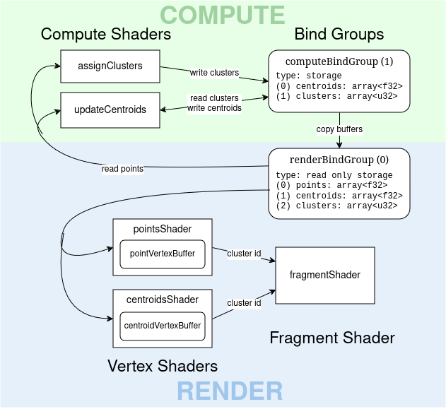
We observe that during running k-means, points remains constant, while centroids and clusters change with each iteration (unless they converge). Our app will be split into two parts: computing and rendering. The solution I came up with is shown in the following diagram.
Render
First, we will implement rendering of the data points as squares and cluster centroids as triangles.
Vertex Buffers
To render data points, we first create a vertex buffer with a square (a square is 2 triangles = 6 vertices).
const pointVertices = new Float32Array([
    -1, -1,
    1, -1,
    1, 1,
    -1, -1,
    1, 1,
    -1, 1
]);
const pointVertexBuffer = device.createBuffer({
    size: pointVertices.byteLength,
    usage: GPUBufferUsage.VERTEX | GPUBufferUsage.COPY_DST
});
device.queue.writeBuffer(pointVertexBuffer, 0, pointVertices);
In a similar way we define the vertex buffer for centroids, which are rendered as bigger triangles.
const centroidVertices = new Float32Array([
    -2, -2,
    2, -2,
    0, 2
]);
const centroidVertexBuffer = device.createBuffer({
    size: centroidVertices.byteLength,
    usage: GPUBufferUsage.VERTEX | GPUBufferUsage.COPY_DST
});
device.queue.writeBuffer(centroidVertexBuffer, 0, centroidVertices);
Next, the layout of vertex buffers is specified: the array contains pairs of coordinates, represented by 4-byte (32 bit) floats.
const vertexBufferLayout = {
    arrayStride: 2 * 4, // 2 x 4 bytes
    attributes: [{ format: 'float32x2', offset: 0, shaderLocation: 0 }]
};
Storage Buffers
Data point coordinates are generated randomly as 2N floats in the range (0, 1). Storage buffers are used rather than uniform buffers as they can hold more data. Uniform buffers have a minimum maximum (yeah, right) size of 64k. Since we copy data into these buffers, we add the COPY_DST usage flag.
const points = new Float32Array(2 * N);
for (let i = 0; i < 2 * N; i++) {
    points[i] = Math.random();
}
const pointsBuffer = device.createBuffer({
    size: points.byteLength,
    usage: GPUBufferUsage.STORAGE | GPUBufferUsage.COPY_DST
});
device.queue.writeBuffer(pointsBuffer, 0, points);
Similarly, 2K floats are generated for coordinates of K centroids.
const centroids = new Float32Array(2 * K);
for (let i = 0; i < N; i++) {
    centroids[i] = Math.random();
}
const centroidsBuffer = device.createBuffer({
    size: centroids.byteLength,
    usage: GPUBufferUsage.STORAGE | GPUBufferUsage.COPY_DST
});
device.queue.writeBuffer(centroidsBuffer, 0, centroids);
To store assigned clusters to points, we create a buffer, but keep it empty.
const clustersBuffer = device.createBuffer({
    size: 4 * N, // 4 bytes x N points
    usage: GPUBufferUsage.STORAGE | GPUBufferUsage.COPY_DST
});
Then we create a bind group and the rendering pipeline. But first we define the layouts, specifying that these buffers are visible to the vertex and compute shaders and read-only storage buffers.
const renderBindGroupLayout = device.createBindGroupLayout({
    entries: [{
        binding: 0,
        visibility: GPUShaderStage.VERTEX | GPUShaderStage.COMPUTE,
        buffer: { type: 'read-only-storage' }
    }, {
        binding: 1,
        visibility: GPUShaderStage.VERTEX | GPUShaderStage.COMPUTE,
        buffer: { type: 'read-only-storage' }
    },{
        binding: 2,
        visibility: GPUShaderStage.VERTEX | GPUShaderStage.COMPUTE,
        buffer: { type: 'read-only-storage' }
    }]
});

const renderBindGroup = device.createBindGroup({
    layout: renderBindGroupLayout,
    entries: [
        { binding: 0, resource: { buffer: pointsBuffer } },
        { binding: 1, resource: { buffer: centroidsBuffer } },
        { binding: 2, resource: { buffer: clustersBuffer } }
    ]
});

const renderPipelineLayout = device.createPipelineLayout({
    bindGroupLayouts: [renderBindGroupLayout]
});
Shaders
The vertex shader for points runs once for every vertex in the vertex buffer for each data point. It returns a struct containing position (like any vertex shader) and the cluster index of a point, passing it to the fragment shader. By using this design, we can use the same fragment shader for both entities. To use storage buffers, we specify their bind group index via @group() and binding indices via @binding(), which were defined in the bind group layout. Inside the main vs function we do a simple transformation, mapping each point position from (0, 1) into the clip space (-1, 1) and stretching the square so it’s 4px big.
struct VertexOutput {
    @builtin(position) position: vec4f,
    @location(0) @interpolate(flat) cluster: u32
};

@group(0) @binding(0) var<storage> points: array<f32>;
@group(0) @binding(2) var<storage> clusters: array<u32>;

@vertex
fn vs(
    @location(0) vertex: vec2f,
    @builtin(instance_index) i: u32
) -> VertexOutput {
    let position = 2 * vec2f(points[2*i], points[2*i + 1]) - 1 + 4 * vertex/${RESOLUTION};

    var output: VertexOutput;
    output.position = vec4f(position, 0, 1);
    output.cluster = clusters[i];

    return output;
}
How did we use RESOLUTION? Oh, we can’t work with JS without resorting to ugly solutions. The shader is stored in a JS file pointsShader.js, which exports it as a string. The constants are imported from config.js.
A similar vertex shader is used for rendering centroids.
struct VertexOutput {
    @builtin(position) position: vec4f,
    @location(0) @interpolate(flat) cluster: u32
};

@group(0) @binding(1) var<storage> centroids: array<f32>;

@vertex
fn vs(
    @location(0) vertex: vec2f,
    @builtin(instance_index) i: u32
) -> VertexOutput {
    let position = 2 * vec2f(centroids[2*i], centroids[2*i + 1]) - 1 + 6*vertex/${RESOLUTION};

    var output: VertexOutput;
    output.position = vec4f(position, 0, 1);
    output.cluster = i;

    return output;
}
Why didn’t we use the same vertex shader since they are so similar? We use different sources to look up the cluster id: the clusters array for points and the instance index for centroids. I thought about solutions to reuse the same vertex shader: either by using separate bind groups or separate fragment shaders, but both alternatives make things uglier.
Next, the fragment shader, which colours everything. The colour of our points is defined by the cluster passed from the vertex shaders. I came up with this function that maps each integer from 0 to K-1 to a unique and hopefully distinct colour.
@fragment
fn fs(@location(0) @interpolate(flat) cluster: u32) -> @location(0) vec4f {
    let normalizedColorId = f32(cluster) / ${K};

    return vec4f(
        fract(1 - pow(normalizedColorId, 2)),
        fract(normalizedColorId + 0.31),
        fract(normalizedColorId + 0.82),
        1
    );
}
Pipelines
Let’s define a pipeline for rendering points and centroids using the shaders defined above. They share the same fragment shader.
const fragmentModule = device.createShaderModule({ code: fragmentShader });
const pointsModule = device.createShaderModule({ code: pointsShader });
const pointsPipeline = device.createRenderPipeline({
    layout: renderPipelineLayout,
    vertex: {
        module: pointsModule,
        buffers: [vertexBufferLayout]
    },
    fragment: {
        module: fragmentModule,
        targets: [{ format: canvasFormat }]
    }
});

const centroidsModule = device.createShaderModule({ code: centroidsShader });
const centroidsPipeline = device.createRenderPipeline({
    layout: renderPipelineLayout,
    vertex: {
        module: centroidsModule,
        buffers: [vertexBufferLayout]
    },
    fragment: {
        module: fragmentModule,
        targets: [{ format: canvasFormat }]
    }
});
Almost there! Now, we create a function for running the pipelines, which is called every 500ms. It begins with the computations (TODO), then clearing the view with black. The points pipeline is ran for pointVertices.length / 2 vertices in N instances: one instance per point. And similarly for the centroids pipeline.
const update = () => {
    const encoder = device.createCommandEncoder();
    // ... compute pass ...
    const pass = encoder.beginRenderPass({
        colorAttachments: [{
            view: context.getCurrentTexture().createView(),
            loadOp: 'clear',
            clearValue: { r: 0, g: 0, b: 0, a: 1.0 },
            storeOp: 'store',
        }]
    });

    pass.setPipeline(pointsPipeline);
    pass.setBindGroup(0, renderBindGroup);
    pass.setVertexBuffer(0, pointVertexBuffer);
    pass.draw(pointVertices.length / 2, N);

    pass.setPipeline(centroidsPipeline);
    pass.setBindGroup(0, renderBindGroup);
    pass.setVertexBuffer(0, centroidVertexBuffer);
    pass.draw(centroidVertices.length / 2, K);

    pass.end();
    device.queue.submit([encoder.finish()]);
}

setInterval(update, 500);
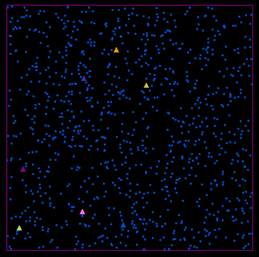
After all this work, all we get is this. The points are all the same colour, because we didn’t compute the assigned clusters yet.
Compute
The computational phase consists of two parts:
- assign: assigning clusters to points, outputting
clusters - update: updating the centroids positions, outputting
centroids
Buffers and Bind Groups
Since storage buffers used in vertex shaders have to be read-only, we create separate read-write storage buffers for the compute phase in a separate bind group. After the computations are done, the results are copied to the read-only buffers and rendered.
const centroidsBufferComp = device.createBuffer({
    size: centroids.byteLength,
    usage: GPUBufferUsage.STORAGE | GPUBufferUsage.COPY_SRC
});
const clustersBufferComp = device.createBuffer({
    size: 4 * N,
    usage: GPUBufferUsage.STORAGE | GPUBufferUsage.COPY_SRC
});

const computeBindGroupLayout = device.createBindGroupLayout({
    entries: [{
        binding: 0,
        visibility: GPUShaderStage.COMPUTE,
        buffer: { type: 'storage' }
    }, {
        binding: 1,
        visibility: GPUShaderStage.COMPUTE,
        buffer: { type: 'storage' }
    }]
});

const computeBindGroup = device.createBindGroup({
    layout: computeBindGroupLayout,
    entries: [
        { binding: 0, resource: { buffer: centroidsBufferComp } },
        { binding: 1, resource: { buffer: clustersBufferComp } }
    ]
});
Since we have to access the data point coordinates in compute shaders (stored in renderBindGroup), both bind groups are passed to the pipeline.
const computePipelineLayout = device.createPipelineLayout({
    bindGroupLayouts: [renderBindGroupLayout, computeBindGroupLayout]
});
Compute Shaders
The assignment phase is run for each point, indexed by the invocation id. We iterate over the centroids and find the closest one, updating the value in clusters. Read only buffers from @group(0) are used where possible.
@group(0) @binding(0) var<storage> points: array<f32>;
@group(0) @binding(1) var<storage> centroids: array<f32>;
@group(1) @binding(1) var<storage, read_write> clusters: array<u32>;

fn dist(a: vec2f, b: vec2f) -> f32 {
    return pow((a.x - b.x), 2) + pow((a.y - b.y), 2);
}

@compute @workgroup_size(${WORKGROUP_SIZE})
fn cs(@builtin(global_invocation_id) id: vec3u) {
    let pointId = id.x;
    let pos = vec2f(points[2*pointId], points[2*pointId + 1]);
    var min_dist = -1.;
    var closest = 0;

    for (var i = 0; i < ${K}; i++) {
        let centroid = vec2f(centroids[2*i], centroids[2*i + 1]);
        let d = dist(pos, centroid);
        if (min_dist == -1 || d < min_dist){
            closest = i;
            min_dist = d;
        }
    }

    clusters[pointId] = u32(closest);
}
The update phase is run for each cluster/centroid. We compute the mean position of points belonging to the current cluster.
@group(0) @binding(0) var<storage> points: array<f32>;
@group(0) @binding(2) var<storage> clusters: array<u32>;
@group(1) @binding(0) var<storage, read_write> centroids: array<f32>;

@compute @workgroup_size(${WORKGROUP_SIZE})
fn cs(@builtin(global_invocation_id) id: vec3u) {
    let centroid = id.x;
    var sum = vec2f(0);
    var num = 0;

    for (var i = 0; i < ${N}; i++) {
        if (clusters[i] == centroid) {
            sum += vec2f(points[2*i], points[2*i + 1]);
            num += 1;
        }
    }

    centroids[2*centroid] = sum.x / f32(num);
    centroids[2*centroid + 1] = sum.y / f32(num);
}
Pipelines
Compute pipelines are created for each step.
const assignModule = device.createShaderModule({ code: assignClusters });
const assignPipeline = device.createComputePipeline({
    layout: computePipelineLayout,
    compute: {
        module: assignModule
    }
});

const updateModule = device.createShaderModule({ code: updateCentroids });
const updatePipeline = device.createComputePipeline({
    layout: computePipelineLayout,
    compute: {
        module: updateModule
    }
});
First, the assignment pipeline is run. The compute shader is run for each point, hence we need Math.ceil(N / WORKGROUP_SIZE) work groups. After this step, the assigned clusters are copied into the read-only buffer. Then, the centroid positions are updated and copied into the corresponding read-only buffer. In both steps we attach both bind groups. After the computations are done, the render pipeline is run.
const encoder = device.createCommandEncoder();

const assignPass = encoder.beginComputePass();
assignPass.setPipeline(assignPipeline);
assignPass.setBindGroup(0, renderBindGroup);
assignPass.setBindGroup(1, computeBindGroup);
assignPass.dispatchWorkgroups(Math.ceil(N / WORKGROUP_SIZE));
assignPass.end();

encoder.copyBufferToBuffer(clustersBufferComp, 0, clustersBuffer, 0, 4 * N);

const updatePass = encoder.beginComputePass();
updatePass.setPipeline(updatePipeline);
updatePass.setBindGroup(0, renderBindGroup);
updatePass.setBindGroup(1, computeBindGroup);
updatePass.dispatchWorkgroups(Math.ceil(K / WORKGROUP_SIZE));
updatePass.end();

encoder.copyBufferToBuffer(centroidsBufferComp, 0, centroidsBuffer, 0, centroids.byteLength);

// ... render pass ...
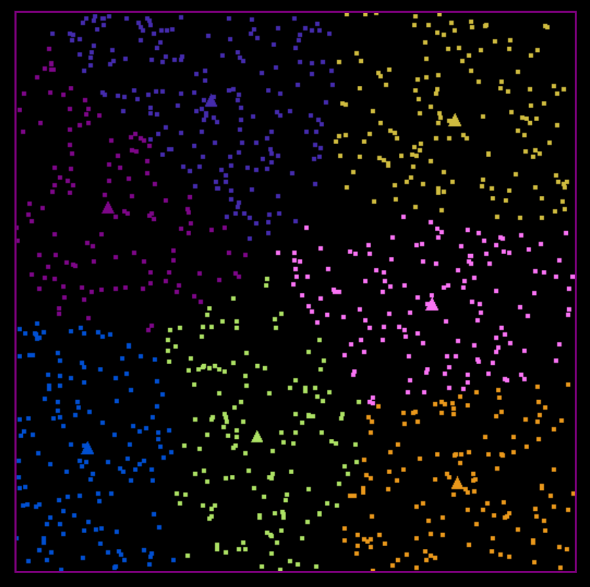
And… it works! You can see the clusters being updated until convergence. Efficiency of the code wasn’t investigated in this post, but it’s a question worth looking into because that’s the whole point of performing computations on the GPU.